top of page
Revit
Project one model: R house
The following are the steps by which I completed project 1
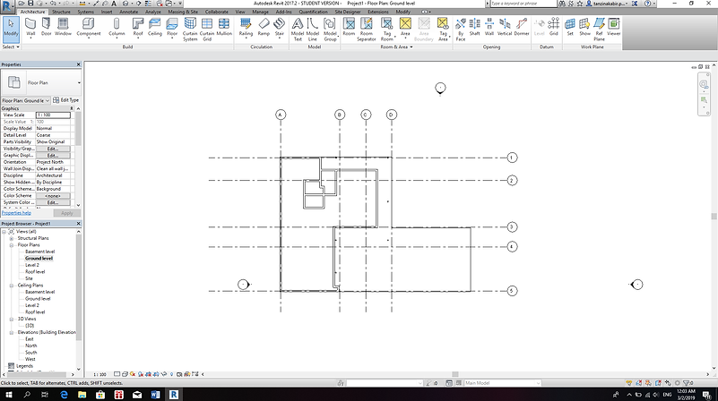
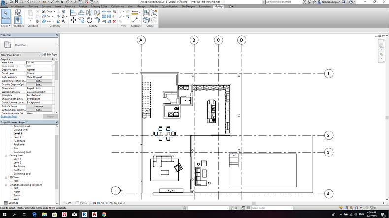
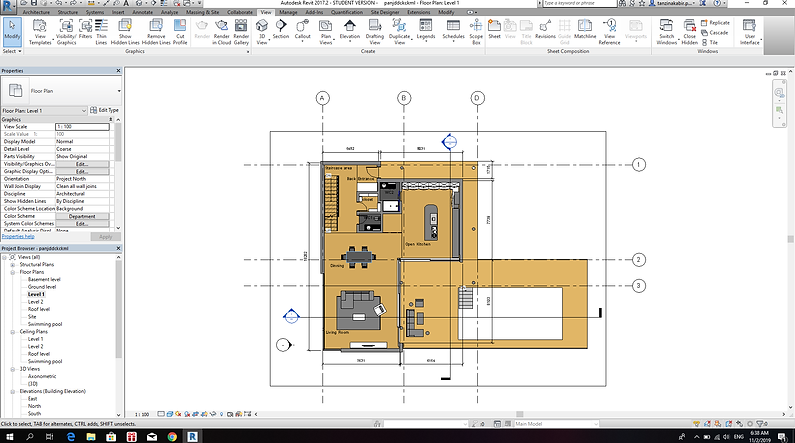
First the floor plan of the ground floor was made. Which is show below.

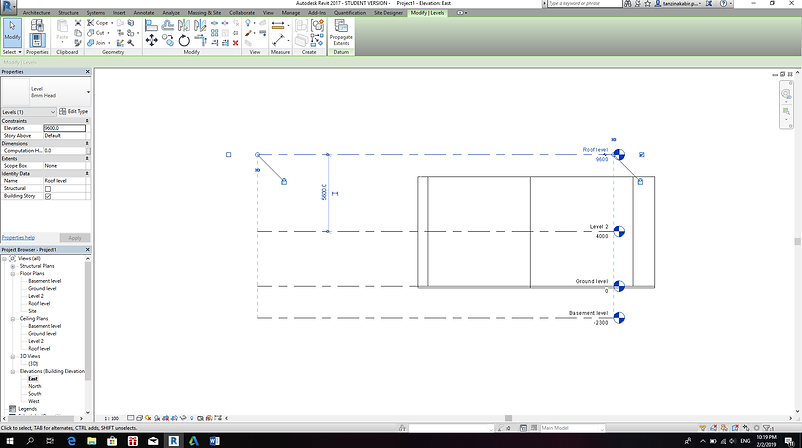
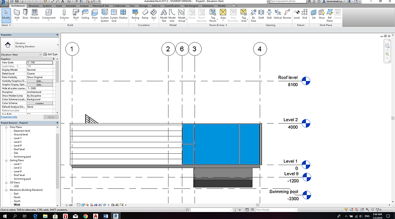
Then the levels were made, on the elevations view, to mark the different level heights.
some lines were drawn to mark the points of the column.

The grid lines were added next, along with the columns.
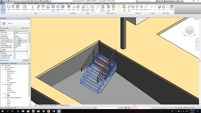
The stair was drawn next,and the risers depth and width had to be adjusted to follow the stair from the actual floor plan.

The view of the stairs in 3D.

The final stair design in 3D shaded.

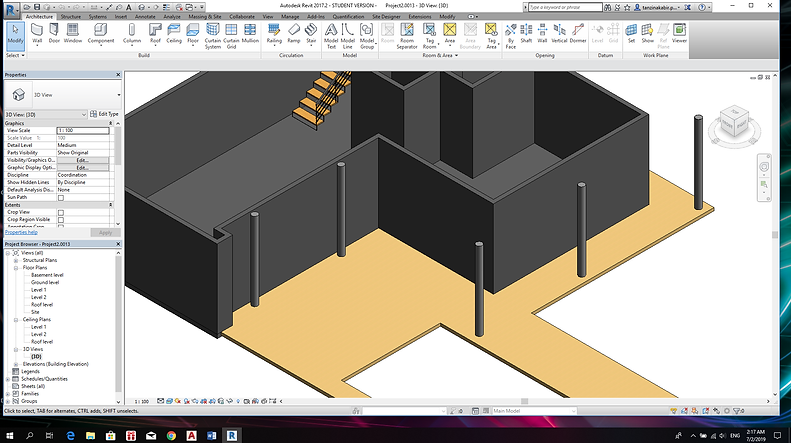
The model so far (shaded) with the area cut out in the deck for the swimming pool.

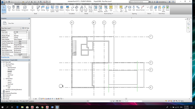
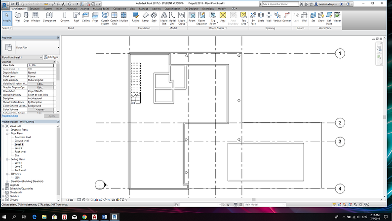
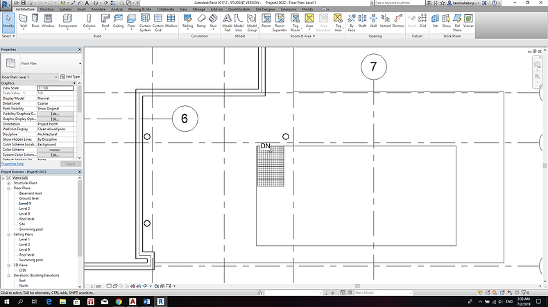
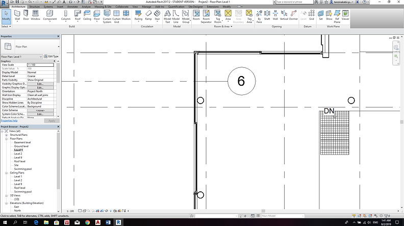
The first floor plan so far
The column diameter has been altered, as shown below.
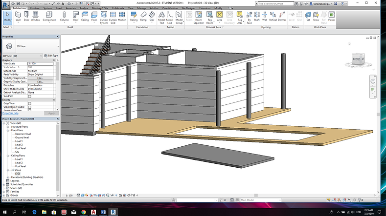
The columns in 3D view
The wall material is being changed.

A new material is being created and edited for the columns.

The wall material was edited to create a look similar to the original house.

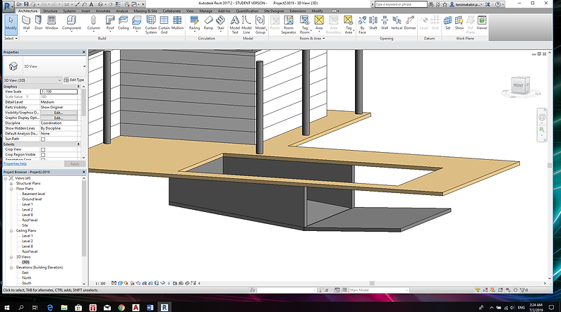
The bottom of the swimming pool being made using floors and the slope arrow.
The Walls were made and then aligned to the floor to create the pool shape.
This is what the pool walls look like in floor plan

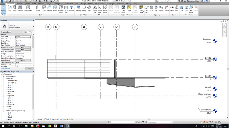
The South Elevation of the pool.
completed pool base

completed swimming pool base in the floor plan

Stairs for the pool. North elevation.

Stairs for the pool. plan view.

The Stairs looked like this at first
The level and offset of the stairs were changed and a material was added.
This is the Swimming pool level's floor plan view

3D view of the stairs complete with the material

The stairs are no longer visible from the north elevation.

Selected a surface of the inside of the pool

Use extrusion and create a volume

Did the same to the other half of the surface
changing the material of the two volumes to resemble water.

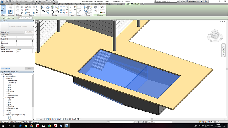
What the 3D looks like with the water
Inserted curtain walls

curtain wall in elevation
curtain wall in elevation

curtain wall in in 3D

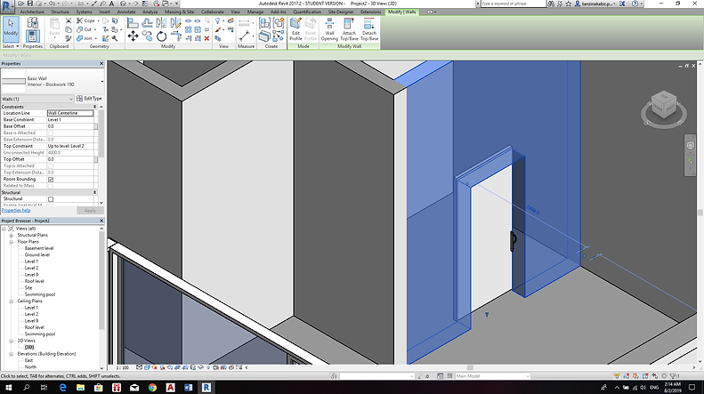
inserted a wall back into 1/3rd of the curtain wall to insert a single sliding door.

Changing the parameters of the door according to the model's floor plan.

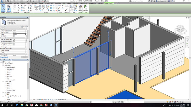
3D with the sliding door
Inserting sliding door on the other side as well.

Changed the parameters the same way to match the original floor plan.
Inserting sliding bar door

Inserting sliding bar door. 3D view
Adding material to the pool interior and joining the two walls to make one surface in order to make one whole extrusion for the water.

Changing Material of the Kitchen to match that of the actual house

Level 1 floor plan with all the furniture inserted
The materials of all the furniture were changed accordingly as well.

Realistic view

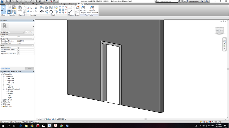
Door Family. All the previous door trims were deleted and new ones are being made.

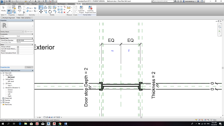
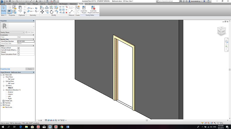
New door frame is created

New door frame is created. 3D view
Making the door panel.
Making the door panel.

Door in the 3D view with the materials changed
Loading and inserting the door in the project

Adding ceiling to the level 1

Making a column family

using Extrusion to change column height according to the plan.

Editing column height

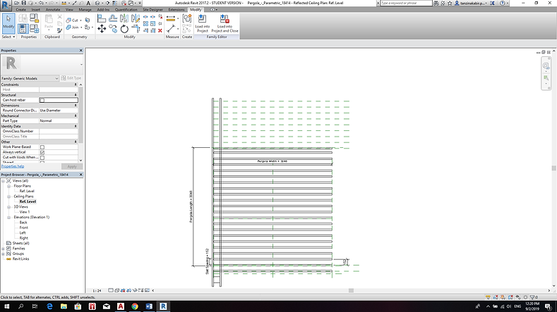
Editing a pregola family to adjust it to the plan dimensions.

Editing a pregola family to adjust it to the plan dimensions. Ceiling view.
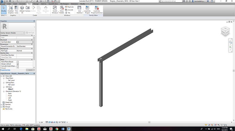
Editing a pregola family to adjust it to the plan dimensions. 3D view After adjusting.

The other bars were not showing up properly attached when loaded into the project, hence they were all deleted but was loaded into a separate family (making the wood bars a separate family) and only the sleet support was left.
Placing the Support bar in the project

Made temporary grid lines to place the wood bars

The Wooden Bars loaded in the project as a different family using the grid lines as a template.

After Adding the basement floor plan and the level 2 plan.
side elevation.
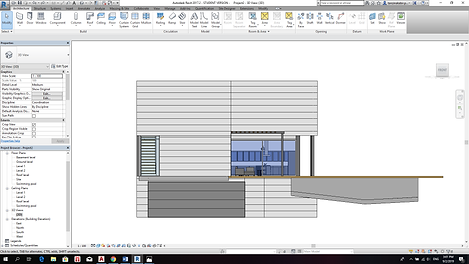
side elevation.

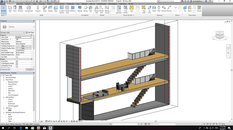
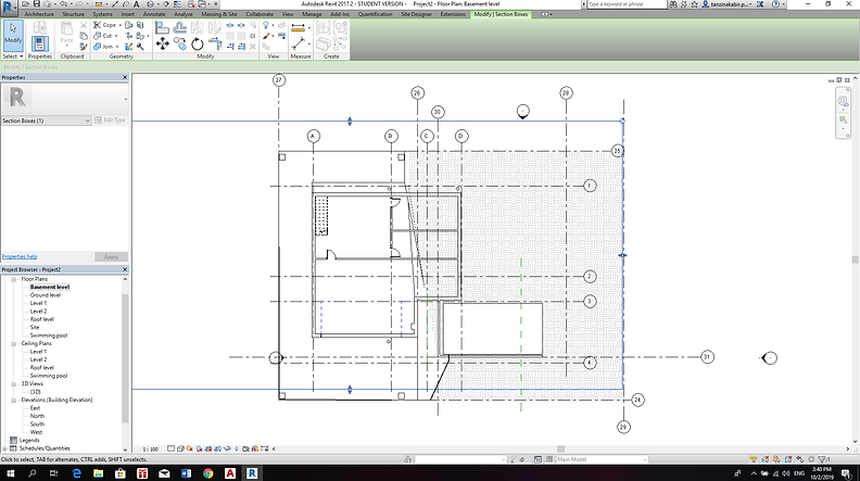
Using the section box to create the railings on level 1 and level 2

Using the section box to create the railings on level 1 and level 2
Creating sections.
Making the roof

Overall site view

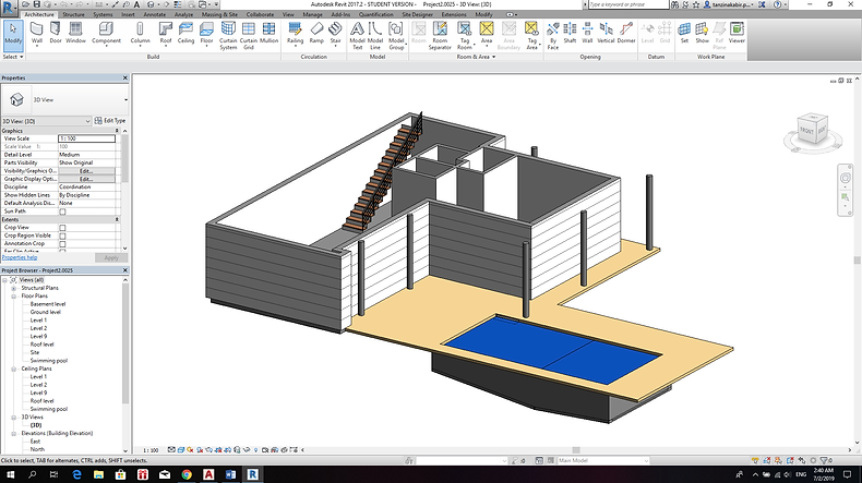
Overall 3D view

Adding a paved path for the backyard

Level 2 completed with the furnitures

Basement completed. The room and door position were guessed from the sections given in the web post.

Basement completed with topography.

Overall Site view with topography.

Topography used for the paved bath to the garage.

Adding a second topography to create the front ground/garden/front yard
3D view of the completed topography

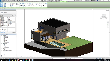
Exploded 3D view

cropping all the floor plans, sections, 3D views, and elevations. Also insertion room tags.

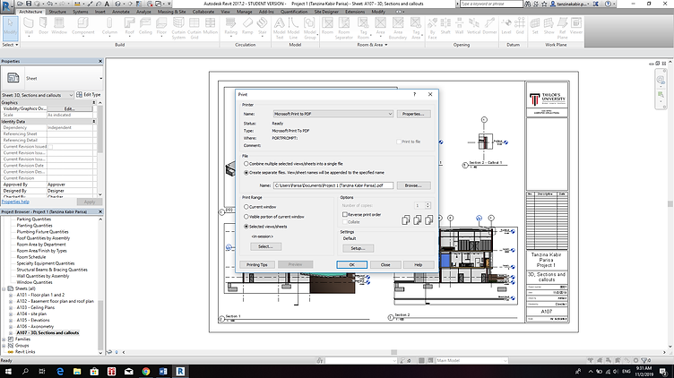
Arranging everything in sheets
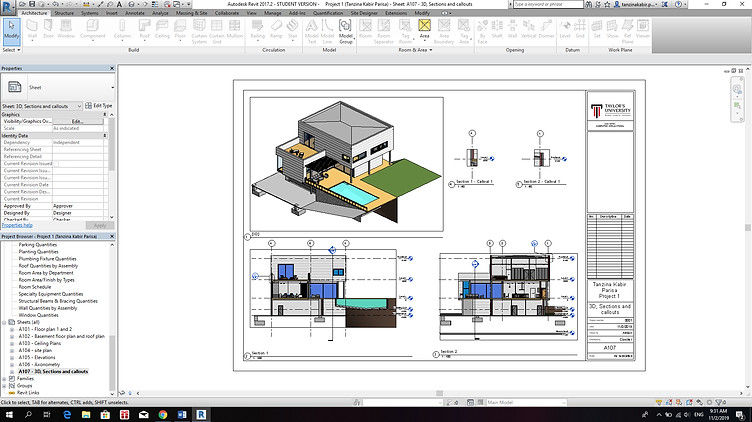
Lastly printing all the sheets in a single pdf for submission.
bottom of page